The central locking system consists of two geared motors built into the driver's door and passenger door locks. System controlled by an electronic module (controller) mounted on a bracket, above the passenger's legs. When one of the doors is closed, the electronic module locks all doors. Similarly, opening one lock unlocks all doors. Locking both doors can be done from inside the car, using the appropriate button located on the door near the lever for opening them. In the case of the version of the car with a mounted remote control receiver, the system works in the same way and the closing and opening is triggered using the remote control.
Central locking
The central locking system consists of two geared motors built into the driver's door and passenger door locks. System controlled by an electronic module (controller) mounted on a bracket, above the passenger's legs. When one of the doors is closed, the electronic module locks all doors. Similarly, opening one lock unlocks all doors. Locking both doors can be done from inside the car, using the appropriate button located on the door near the lever for opening them.
In the case of the version of the car with a mounted remote control receiver, the system works in the same way and the closing and opening is triggered using the remote control.
As the Italian manufacturer has accustomed us, there are several versions of the installation that changed in the course of production. The installation of the central lock occurred with and without the factory alarm. In addition, a number of changes have been made related to the update of the electrical installation, in which the fuse box on the stringer was changed to one mounted directly on the battery.
Below we have described all the cases known to us.
Basic version
Elements included in the central locking system are located in the doors, under the hood, in the dashboard and cabin. In the drawing and diagram you can also see universal elements included in many different systems such as battery, fuse box, etc.
24 - fuse box "maxi"
31 - fuse box - connection module
39 - battery weight
40 - battery
41 - connector (board harness to driver's door harness)
51 - connector (board harness to passenger door harness)
55 - dashboard weight left
56 - dashboard weight right
75 - door closing mechanism - left
76 - door closing mechanism - right
77 - controller - door lock
Arrangement
Electrical diagram
In the documentation of the Italian woman there is only a diagram of the central lock with an alarm. It presents many options which makes it very difficult to read, track calls. We have prepared a diagram containing only central lock connections, without an alarm system as in most of our cars.
Lock with alarm
This version is enriched with a factory alarm, which is quite rare in our cars because it was mounted as an additional option and was quite expensive.
In the description, we do not focus on the alarm itself, but on the central lock, so you should not look for sensors and others in the diagram. The alarm is connected to the circuits of the central lock to determine the closing / opening status of the door.
Elements included in the central locking system are located in the doors, under the hood, in the dashboard and cabin. The drawing and diagram also show universal elements included in many different systems such as battery, fuse box, alarm control unit, etc.
24 - fuse box "maxi"
31 - fuse box - connection module
32 - connector (board harness to front harness)
33 - ignition switch - ignition
39 - battery weight
40 - battery
48 - alarm system control unit
41 - connector (board harness to driver's door harness)
51 - connector (board harness to passenger door harness)
55 - dashboard weight left
56 - dashboard weight right
75 - door closing mechanism - left
76 - door closing mechanism - right
77 - controller - door lock
82 - connector (board harness to rear harness)
101 - switch under the steering wheel
117 - central ceiling lamp
125 - fuse - 20A (cab right)
141 - main rear weight
Arrangement
Electrical diagram
The diagram contains all connections for the central lock system in the version with factory alarm. Both door closing mechanisms (75 and 76) have here connected closing switches (wires in color V - green) and switches informing the alarm about the position of the lock (wires in color A and B). They allow you to arm the alarm as soon as the door locks are successfully slammed.
In this version, the main fuse box (24) is located on the left side actor under the hood. In addition, the diagram shows the connections in the ignition and the switch under the steering wheel.
Lock with alarm - Stage A
In 2000, the Italian manufacturer introduced a number of changes. The appearance of a third stop light or a change in the engine control computer are just some of many. In the case of central locking, the following factors have an impact here:
-
Fuse box change "maxi" (24)
-
development of the color scheme of electrical wires
-
changes in wiring harness connections due to change of motor management
As above, we present a version enriched with a factory alarm, which is quite rare in our cars because it was mounted as an additional option and was quite expensive.
In the description, we do not focus on the alarm itself, but on the central lock, so you should not look for sensors and others in the diagram. The alarm is connected to the circuits of the central lock to determine the closing / opening status of the door.
Elements included in the central locking system are located in the doors, under the hood, in the dashboard and cabin. The drawing and diagram also show universal elements included in many different systems such as battery, fuse box, alarm control unit, etc.
24 - fuse box "maxi"
31 - fuse box - connection module
32 - connector (board harness to front harness)
33 - ignition switch - ignition
39 - battery weight
40 - battery
48 - alarm system control unit
41 - connector (board harness to driver's door harness)
51 - connector (board harness to passenger door harness)
55 - dashboard weight left
56 - dashboard weight right
75 - door closing mechanism - left
76 - door closing mechanism - right
77 - controller - door lock
82 - connector (board harness to rear harness)
101 - switch under the steering wheel
117 - central ceiling lamp
125 - fuse - 20A (cab right)
141 - main rear weight
Arrangement
Electrical diagram
The diagram contains all connections for the central lock system in the version with factory alarm. Both door closing mechanisms (75 and 76) have closed sensors connected here, but the colors of the wires for the left and right sections (V and VN wires) are distinguished. They allow you to arm the alarm as soon as the door locks are successfully slammed.
In this version, the main fuse box (24) is located on the battery. This change also forced the reorganization of the fuse box terminals in the cabin (31). The colors of the wires in the alarm control unit harness have also been changed (48).
In addition, the diagram shows the connections in the ignition and the switch under the steering wheel.
A new welding point for the AR cable has been added and the connection of the rear ground has been simplified.
Lock Driver (77)
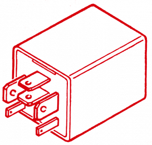
 The central lock controller is made in the form of an electronic module in a plastic housing with pins in the form of a series of knife contacts the same as in the case of car relays. The two contacts S1 and S2, which are used for control, are made as slightly smaller.
The control module is equipped with a protection system that temporarily cuts off the power supply to the geared motors for 15-35 seconds from the moment when the door open/close command occurred. This avoids overheating of the geared motors (75, 76) if the relays remain closed. In this case, the integrated system performs at least three door opening/closing cycles in less than 15 seconds and a so-called stop is activated. The stop keeps the door locks open for 95-145 seconds.
Output
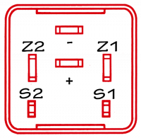
The controller pinouts are divided into three groups: power, inputs and outputs.
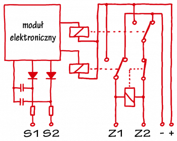
The control inputs S1 and S2 are connected to the limit switches in the door geared motors. Thanks to this, it is possible to control closing and opening as a function of the current position of the locks.
Outputs Z1 and Z2 direct current to both geared motors connected in parallel. The relay insert inside the controller changes the direction of current flow in the geared motors, thus forcing the locks to close or open.


Z1 - geared motor control Z2 - geared
motor control S1 - closing
control input S2 - opening
control input + - power supply directly from the battery
- - power supply ground
Technical Specifications
| operating voltage | 6 ÷ 18 volts |
| parametric voltage | 10 ÷ 15 volts |
| current consumption during "stand-by" time (at 12 V) | < 0.5 mA |
| contact cleaning current | 10 mA |
| Response time | 20 ÷ 40 sec |
| temperature range | -30 ÷ +85 °C |
| Operating temperature range | -30 ÷ +90 °C |
| parametric temperature range | -30 ÷ +65 °C |
| Storage temperature range | -40 ÷ +105 °C |
| Force response time | 50 ms |
| serial resistance of control inputs (S1, S2) | 25 Ω |
| parallel resistance of control inputs (S1, S2) | 2 kΩ |
Part numbers
| Part number | description | Modifications |
|---|---|---|
| 46724934, 46476321 | Passenger door lock | |
| 46724935, 46476322 | Driver door lock | |
| 46731405 | Passenger door lock | C2754 - New Dust Protection Locks (Date: 15/04/1997, #0027703) |
| 46731406 | Driver door lock | D2754 - New locks with dust protection (Date: 15/04/1997, #0027703) |
| 46476319 | Passenger door lock | E223, E228 - Auto alarm, electronic door lock |
| 46476320 | Driver door lock | E223, E228 - Auto alarm, electronic door lock |
| 51752580 | Lock controller | 09.10.2013 - change to a new OEM number 51841013 |